Sunday, April 15, 2018

Week 13 (04/09/2018 - 04/15/2018)

In this week, the following tasks were done:

  • We connected our device to the voltmeter and a battery, then we turned on our device to measure the current used by our system. During the experiment, the motor used up to 6 amps current. The picture below shows the experimental setup:
  • Next, we added the Teflon on the device. 
    • We first added the Teflon to each ridge as it is shown in the pictures below:


    • Then after, we covered the whole top part of the device by the Teflon. Staples were used to attach the Teflon on the device. The pictures below show how it was done:


A access point needed to be made for the cables of the motor as shown bellow:


Once the access point was made the synthetic leather was attached around the top layer of the device with the cushion within it as shown bellow:


The base layer was then used to have the synthetic leather attached on the sides of the base as shown bellow: 


Furthermore, Velcro was attached to the top layer and base layer of the device. This served the purpose to attach both components and have the ability to easily show the components within the device if needed. This process is shown bellow:


The finalized product is shown in the picture bellow:


Wednesday, April 4, 2018

Week 11 and 12 (03/26/2018 - 04/08/2018)

In the 11th week which started 03/26 and ended 04/01, the followings were done:

  • We had a new flange collar, and since it has four holes instead of three, we had to use a new torque plate and to create new holes in it. The pictures below show how we created the new holes in the torque plate:
    • We first searched where the center of the torque plate was located by using the below machine

    • Then, we made a center hole

    • Next, we made the four side holes in the torque plate by using a hole press machine as it is shown in the picture below

    • We attached the new torque plate and flange collar to the disk, as the pictures below show it:


  • Since the new flange collar was not strong enough, we decided to create a new flange collar which is able to hold the higher loads. The picture below shows the weak and the strong flange collar:

  • This is the ways we created the strong flange collar:
    • We used the lathe machine to create the cylindrical upper part of the flange collar

    •  The base part of the flange collar was sanded in order to have a smooth and clean finish as we see it in the below picture:

    • Then we cut it. Below is the picture of the part after the cut:


    • Next, we made holes in the base part of the flange collar as we see it in the below picture:

    • Here is the picture of the strong flange collar

In the 12th week which started 04/02 and end 04/08, the followings figures show the testing for flow rate:

  • For the testing,  a gelatin was prepared and tubes were set into it. The picture below showed it:
T
 The tubes were sealed before making the gelatin in order to prevent from any gelatin going inside the tubes. Therefore, we had to open the tubes from each end to allow water to get through.


We measured how much water was drained with no movement of disc rotation. We measured 4 ml.


The gelatin was placed on the top of the disc with the tubes making contact with the disc. A plastic sheet was placed over the device to collect the water.


The disc was rotating for 30 seconds until the gelatin split into two pieces.


We collected the water that was drained for 30 seconds of rotation and its collection was 6 ml. It proves that our device does promote flow.


Monday, March 26, 2018

Week 9 and 10 (03/12/2018 - 03/25//2018)


Assembly of Base

Alex and Carlos worked on assembling the base of the device together with the rest of the components.


Mount Flange Collar Failure During Testing

During testing a load of 70 lbs was applied on top of the disk while the device was running. However, the mount flange collar was not strong enough to handle the torque of the motor and the friction caused by the applied force. It is assumed that due to the adjustments made to the flange, the flange became weaker, and due to it being made of aluminum it was not ideal flange to use for the device. New and better flange collar was order and will be implemented in the future.

Testing and Verification

4 soft ¼” tubes were inserted into a 12” OD, 5” deep cylinder of ballistic gel. These tubes empty into a hollow core where a collection tray catches the water. The device was run for 1 minute and 5 ml of water was collected. 180 lb of force was applied to the top of the ballistic gel during testing, which caused fracturing of the gel. The device was not operated by the motor but rather it was manually turned during testing.


Wednesday, March 7, 2018

Week 8 (3/5/18-3/11/18)

Testing and Verification Plan

Requirement: Must not induce over 33 mmHg on arteries for more than 1 hour; Must mitigate relative pressure against the bony prominences in the buttocks (sacrum/ischium). Pressure distribution must alternate to allow regular tissue decompression. Maximum pressure at the ridge must not exceed 10% of the user’s body weight per square centimeter. Minimum pressure at the decompression areas must not exceed 5% of the user’s body weight per square centimeter.
Test Procedure: A flexible pressure pad connected to a computer will be placed between the operating device’s cushion and a seated test user. The pressure at the cushion interface will be measured, specifically the ridges as they turn under the bony prominences. The pressure pad’s sensor precision must be experimentally verified by comparing the sum of each sensor’s pressure * total area to the expected weight across the device’s surface.

Requirement: Device should provide a fan-like pressure gradient which accommodates fluid flow in vascular tissue near the cushion interface. Must generate non-zero flow through surface vascular tissue while disc is turning.
Test Procedure: A tissue-like gelatin material will be impregnated with horizontal layers of radially oriented ductile plastic tubing filled with water and marker particles. The marker particles will be set at the outer edges of the tubing. The gelatin model will be placed on the disc with at least 150 lb. of weight across its top surface. The device will be turned on and allowed to run for up to 2 minutes. Net particle movement will act as a measure of flow. Non-zero flow toward the center of the disc is the goal. 

Requirement: Device should be comfortable.
Test Procedure: The cushion interface pressure gradient test quantitatively fulfills this requirement. Qualitative feedback from users will also be considered. 

Requirement: Device weight should not exceed 50 lb.
Test Procedure: Prototype (without its display base and battery) will be weighed and final prototype materials and design may need to be altered. 

Requirement: Device dimensions must not exceed 42x36x26 in.
Test Procedure: Prototype (without its display base and battery) will be weighed and final design may need to be altered. Note that the device’s dimensions are already adjustable for various seat sizes. 

Requirement: Cushion must regulate contact heat and humidity at cushion interface.
Test Procedure: Heat and vapor dissipation testing protocols are defined in RESNA/ISO standards. If a pre-approved wheelchair cushion and seat cover are being used, this requirement has already been verified and does not need to be tested. 

Requirement: Device must be able to withstand 200 lb. across its seat surface.
Test Procedure: Calculate the load response of the device in its final fabrication material using available experimental material information. Material must be able to handle prescribed loading with a minimum safety factor of 1.5 

Requirement: Wheelchair range must not be reduced by more than 40%.
Test Procedure: Calculate device power draw for specific wheelchairs on the market and in current use. If a battery upgrade is required to fulfill this requirement, its description (make, cost, size) must be included in test results.

Additional References


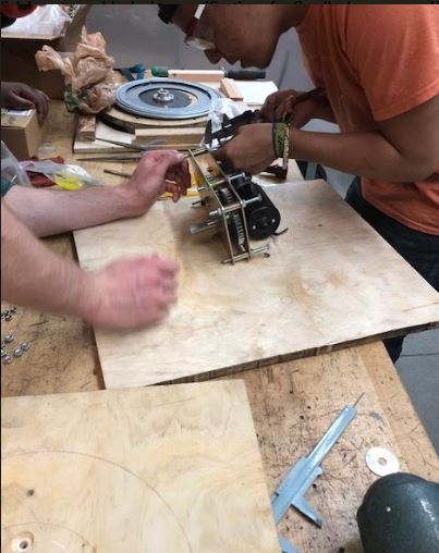
Another New Base Created

On Monday, our team decided to create new base due to the disc not moving.
The pictures below show the team working on a new base to center the motor.

             
 The figure above shows our teammate creating the holes on base for the turntable using a drill press


The figure above shows one teammate using a jigsaw to create a cut for flange collar access


The figure above shows the motor and disk connected as a whole

The figure above shows a teammate using a hack saw to cut the machine screws that were slightly longer (1/4-20-4" to 3-1/2)


The figure above shows a teammate fastening the turntable on the base with wood screws


Although, the team created a new base, the disk was not turning as expected. There was issues with the alignment.


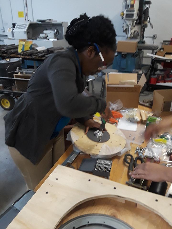
On Tuesday, the team decided to create another base. Our team spoke to our adviser and the team determined that the shaft of the motor needed to be centered to the center point of the turntable to have the disc turning accurately.
The figures below show how the team accurately measured the turntable to its center point in order to place the shaft of the motor correctly. 


The figures above how the center point of the turntable was measured.

The figure shows how the points at the end of the circle were accurate, therefore, having the center of the turntable


The figure above shows machine screws  being placed to get accuracy on where the motor is aligned.


Monday, March 5, 2018

Week 7 Spring ( 2/26/2018-3/4/2018)

In this week, we did a new base for the motor.

Measuring the right dimensions where the turntable will be located

 Drawing a circle where the edge of the turntable would be parallel to

Monday, February 26, 2018

Week 6 Spring ( 2/19/2018-2/25/2018)

In this week, we worked on assembling all the parts together.

We drilled the middle hole of the flange collar to make it bigger so that the motor shaft can fit in it.

We drilled new side hole in the torque plate. Those holes were used to attach the flange collar to the torque plate. After, we put the flange collar, the torque plate and the disk together

We put the tape and the glue on roll on the parts  where the teflon was going to be attached

After, the teflon was put on the top of disk

Next, the new holes were drilled in the base where the screws of the motor would be. A side cut was also made which would be used to tighten the flange collar.

The screws of the motor were changed. In the picture above, the screw on the left is the one for the motor, but since it was not tall enough, it was replaced by the one on the right

The motor with the new screws. The middle right screw was not able to be replaced because the arrangement of the motor parts was not convenient to us to do the replacement of it 

After, the motor was attached to the base

The turntable was attached to the riser and after, they were put together with the base and its support

Next, the holes were drilled in the support cushion. Those holes were used to attach the support cushion to the design

The picture of the final design with all parts on it