Sunday, April 15, 2018

Week 13 (04/09/2018 - 04/15/2018)

In this week, the following tasks were done:

  • We connected our device to the voltmeter and a battery, then we turned on our device to measure the current used by our system. During the experiment, the motor used up to 6 amps current. The picture below shows the experimental setup:
  • Next, we added the Teflon on the device. 
    • We first added the Teflon to each ridge as it is shown in the pictures below:


    • Then after, we covered the whole top part of the device by the Teflon. Staples were used to attach the Teflon on the device. The pictures below show how it was done:


A access point needed to be made for the cables of the motor as shown bellow:


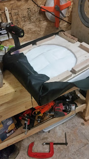
Once the access point was made the synthetic leather was attached around the top layer of the device with the cushion within it as shown bellow:


The base layer was then used to have the synthetic leather attached on the sides of the base as shown bellow: 


Furthermore, Velcro was attached to the top layer and base layer of the device. This served the purpose to attach both components and have the ability to easily show the components within the device if needed. This process is shown bellow:


The finalized product is shown in the picture bellow:


Wednesday, April 4, 2018

Week 11 and 12 (03/26/2018 - 04/08/2018)

In the 11th week which started 03/26 and ended 04/01, the followings were done:

  • We had a new flange collar, and since it has four holes instead of three, we had to use a new torque plate and to create new holes in it. The pictures below show how we created the new holes in the torque plate:
    • We first searched where the center of the torque plate was located by using the below machine

    • Then, we made a center hole

    • Next, we made the four side holes in the torque plate by using a hole press machine as it is shown in the picture below

    • We attached the new torque plate and flange collar to the disk, as the pictures below show it:


  • Since the new flange collar was not strong enough, we decided to create a new flange collar which is able to hold the higher loads. The picture below shows the weak and the strong flange collar:

  • This is the ways we created the strong flange collar:
    • We used the lathe machine to create the cylindrical upper part of the flange collar

    •  The base part of the flange collar was sanded in order to have a smooth and clean finish as we see it in the below picture:

    • Then we cut it. Below is the picture of the part after the cut:


    • Next, we made holes in the base part of the flange collar as we see it in the below picture:

    • Here is the picture of the strong flange collar

In the 12th week which started 04/02 and end 04/08, the followings figures show the testing for flow rate:

  • For the testing,  a gelatin was prepared and tubes were set into it. The picture below showed it:
T
 The tubes were sealed before making the gelatin in order to prevent from any gelatin going inside the tubes. Therefore, we had to open the tubes from each end to allow water to get through.


We measured how much water was drained with no movement of disc rotation. We measured 4 ml.


The gelatin was placed on the top of the disc with the tubes making contact with the disc. A plastic sheet was placed over the device to collect the water.


The disc was rotating for 30 seconds until the gelatin split into two pieces.


We collected the water that was drained for 30 seconds of rotation and its collection was 6 ml. It proves that our device does promote flow.