Tuesday, November 28, 2017

Week (11/27/17-12/3/17)

Brainstorming for Final Presentation

Students were brainstorming ideas and assigning one another different task to accomplish for the final presentation.

Our goals for the device: 

Investigate the base on where the disk is going to be placed

Find a motor unit that can withstand the pressure given

 The figure above shows the task given to each person on the team and are future goals for our device

Schematic of Base


The figure above shows a rough schematic of the base with the motor located within the base. The motor unit will have a shaft on a wheel to turn the disk. The lazy susan attached to the disk will make the disk run smoother. Underneath the disk another base plate will be attached in order to have more distance so that the shaft on wheel can fit.

Friday, November 24, 2017

Week 10 (11/13/2017 - 11/19/2017)

In this 10th week we did these:

  • On Monday the 13th November 2017, we brainstormed about how we will do a shakedown similar to the human capillary. The picture below shows the formulas that we thought to use in imitating the flow in the human capillary (formulas are on the down right side of the whiteboard)
  • On Tuesday the 14th November 2017, we brainstormed different ideas and then after we chose the shakedown test that we would use. The pictures below show those ideas. The 3rd picture shows the prototype we chose.


  • On Thursday the 16th November 2017, the shakedown was performed. The picture below shows the specifications
    • The pictures below show the setup, the before and after the shakedown test.


    • Explanation: The test was run for 2 minutes and completed 32 rotations. The tube was placed across half of the tube with markers on the outside and the other end at the center of the disc. The markers were inside the tube at the beginning of the test and they moved inwards through the tube during the test. The resistance that the markers faced was based on the tube itself which had a 1/8inches inner diameter and 12 inches long.
                   The picture with two tubes side by side shows the before and after marker positions

Monday, November 13, 2017

Week 9 (11/6/2017 - 11/12/2017)


In this week, we met twice to work on the Deliverable 5_b and to do the shakedown test.
  • The first meeting was on Tuesday (11/7/2017) and at that time we brainstormed ideas for the Deliverable 5_b. The pictures below show the ideas that we brainstormed:

  • The second meeting was on Friday (11/10/2017) and we created the prototypes and then after did the shakedown test.
    • We first drilled the circle wood that was supposed to rotate and to hold the weight
    • Then after we used the screws to attach a double squared metal (with a circular hole inside) to the circular wood. The double squared metal is supposed to attach the circular wood to a rectangular base wood, and it has ball bearing around the circumference of its circular hole which allows the circular wood to rotate about the base. After attaching the double squared metal to the circular wood, it looked like this: 
    • After, we drilled the 3D printed mountain waved lobe. The mountain waved lobe was supposed to go on the top of the circular wood to make a shape similar to a donut shape.The first picture below shows how the mountain waved lobe looked like, and the second picture shows the way we drilled it.

    • Next, we drilled the holes in the circular wood where we would enter the screws that would attach the mountain waved lobe to the circular wood.

    • After, we went to Engineering shop at ABPK. Arriving there, we shaped well the hole in the mountain waved lobe, where the screw was supposed to enter.
    • We smoothed out the bottom part of the mountain waved lobe to make it flat.

    • We adjusted the size of the screws by cutting the extra length of them (they were too long) after we assembled the parts
    • The final assembly of the rotating part looked like this

    • Next, we drilled the rectangular base.

    • We attached the base to the rotating part, and it looked like this:

    • After, we taped it to smooth out the edge of the mountain waved lobe.

    • After taping it, the part looked like this:

    • Next, we came back to wet lab to do the shakedown test. We first added the soap on our rotating disk to make a lubricating layer.

    • We took a clear bag, we added 9 bakers of water with each baker having 1000ml, we cut small pieces of a red post-it note and we added them to the water after we closed the bag. A picture of the setup is shown below:

    • Below is a video that shows how the small pieces were distributed in the water before the shakedown test.

    • We did the shakedown test by rotating the disk for one minute. We did 12 revolutions in one minute. The video of the distribution of the small pieces after the shakedown test is shown below:

    • In total there were 50 lbs mass on to the top of the disk, which is approximately close to the upper body mass.


Sunday, November 5, 2017

Week 8 (10/302017 - 11/5/2017)

This week's focus was to perform a shakedown test on the functionality of the disk and gather equations that will lead to improvements to the design.

Shakedown Test Video:


Shakedown Test Description and Calculations

The disk is placed over a motorized rotating shaft that requires 0.28 amps to rotate the disk. During the shakedown test it was recorded that for the disk to complete one revolution, it required 6.3 seconds. Therefore, the following calculation can be made:

When the pressure applied with the upper body of a 170-pound person on the disk, the following calculations can be made:


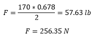
  • Actual force applied to the disk:

  • -          If the radius of the disk is 0.0889, the cross-sectional area of the disk is calculated as follows:
  • With the surface area of the disk being 0.02484 m^2, the pressure applied to the disk is as follows:

When the disk is rotating without any pressure applied, the current required to rotate the disk is 0.28 amps, however, when the pressure is applied to the disk the current required to rotate the disk is 0.5 amps. Also, the voltage is a constant of 23.7 volts. Therefore the following equations can be made:
  • Unloaded power draw:
  • Loaded power draw:
Therefore, the power increase is calculated by the following equation:
The maximum power output for the motor is 30 watts. While we used only 39.5 % of the maximum power output of the motor is can be concluded that a motor with half that power would be sufficient to use for our design.

From the shakedown test, it was observed that all the markers spread out within a fluidized bag, were relocated towards the center of the disk within 47 seconds of disk rotation.

Therefore the following equation can be made:


From a common wheelchair battery of 12v 35 aH, can make the following calculation of how much energy is contained within the battery:

If we plan on running the loaded disc for 1 minute each thirty minutes, this consumes 711 Joules each cycle.

Since this happens 2 times per hour for 16 hours, each day is consumes 22752 Joules

Therefore we can say that each day our device consumes less than 2% of the wheelchair’s total battery life.
Brainstorming Session from October 30, 2017:


From this brainstorming session, we determined three different designs from which the group will agree to work further based on the results of the shakedown test. 

The first design (left) is a design that simulates a movable hammock type of seat that will be mechanically moved in order to alternatively distribute the weight of the wheelchair user to prevent ulcers. 

The second concept design (middle) is a design that is based on a disk with a void in the middle, which will leave the most concentrated pressure points from having minimum contact to the disk as possible while the rest will be massaged by the disk to distribute the blood circulation towards the such pressure points. 

The third desgin, deals with the same concept as the second one, however, it leaves an extra void at the bottom to not cause constant pressure on the legs. This design will work with rollers that will be pushed up by a wedge which will cause blood circulation towards such pressure points.